
- #Arduino pro mini pinout diagram mac os#
- #Arduino pro mini pinout diagram serial#
- #Arduino pro mini pinout diagram update#
- #Arduino pro mini pinout diagram android#
- #Arduino pro mini pinout diagram software#
#Arduino pro mini pinout diagram update#
This new update brings support for 10-bit HDR, lossless USB audio, and more.
#Arduino pro mini pinout diagram android#
The board can simply attach to a USB bus and will appear as a standard COM port.TL DR Android 14 Beta 2 has arrived for Google Pixel phones.
#Arduino pro mini pinout diagram serial#
This is a great little tool for embedded systems that require a serial connection to a computer. It features:This is the CP2102 (6-pin) USB 2.0 to TTL UART serial converter module. Due to its fast communication, stability, reliability, and safety, it is an ideal choice for industrial control equipment and/or applications with high communication requirements. Limited availability.25malx vusxx The USB TO RS232/485/TTL is very easy to use, fully automatic transceiving without delay. Elegoo 120pcs Multicolored Dupont Wire …USB to TTL / USB-TTL /STC microcontroller programmer / PL2303 in nine upgrades plate with a transparent cover Compatible with ARDUINO, RASPBERRY PI, AVR, PIC, 8051, …Adafruit Industries USB to TTL Serial Cable Protect and Support Free 60 Day Tech Support May be returned within 30 days of purchase* Learn More $15.99 18 MINUTE PICKUP Not Available MAP YOUR TRIP Add to List ANYTIME SHIPPING Ship This Item Fastest Delivery Mar, 17 Usually ships in 5-7 business days.
#Arduino pro mini pinout diagram mac os#
#Arduino pro mini pinout diagram software#
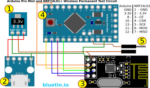
Has a USB support (Micro-USB Connector), and FTDI forms the USB connectionīoth boards run on Arduino software and thus can perform in equal measure. Operating Voltage- 7V to 9VInput Voltage- 5VĪnalog Input pins count – 6 No analog output PinsĪnalog Input count- 8 No analog output pins What are the Differences between Arduino Pro Mini vs Nano?įig 2: Both boards are useful in DIY projects FeaturesĪTMega328P and ATMega168P microcontroller It provides a reference voltage to the board It switches the LED ON and OFF depending on the board’s condition. These are essential in initiating an interrupt They are useful in receiving and transmission of the board’s TTL serial data. They maintain the board’s analog input voltage between 0V and 5V. It is useful in resetting the microcontroller. Vin is the input voltage pin connecting to an external power source of 7V to 12V. Next, we have the 5V for supplying a regulated power supply voltage. Also, there’s the 3.3V pin that receives minimum voltage from the voltage regulator. Lastly, GND is the board’s, Ground Pin. Lastly, there’s a RESET pin for setting the microcontroller.Moreover, we have the Data Terminal Ready (DTR) pin for resetting the board and inputting the bootloader for the Arduino pro mini programming.In addition, there’s Pin I2C which enables I2C communication.The LED goes on when the pin is high and off when the pin is low. Further, we have Pin 13, which features a built-in LED.These are imperative in supporting SPI communication. Also, there is Pin 10 (Slave Select), Pin 11 (Master Output/ Slave Input), Pin 12 (Master Input/ Slave Output), and Pin 13 (Serial Clock).You use these pins with the analogWrite function to give an 8-bit PWM output. Triggering these pins prompts an interrupt. Next, we have Pin 2 and 3 that function as external interrupts.Pin 0 and Pin 1 are UART pins/ serial pins for serial communication or receiving and transmitting TTL serial data, respectively.The microcontroller features 14 digital input/output pins whose functions are as follows: nanoįig 1: A car robot toy made using an Arduino board Arduino Pro Mini Pinout

We’ll explore the features of these two at length.

Instead, Arduino Pro Mini vs Nano is a handy alternative. Often, many people opt for the Arduino Uno, but where fitting in a small size is necessary, this version is not feasible. The Arduino board is one of the most popular microcontrollers due to its versatility.


 0 kommentar(er)
